-
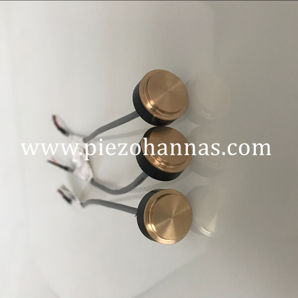
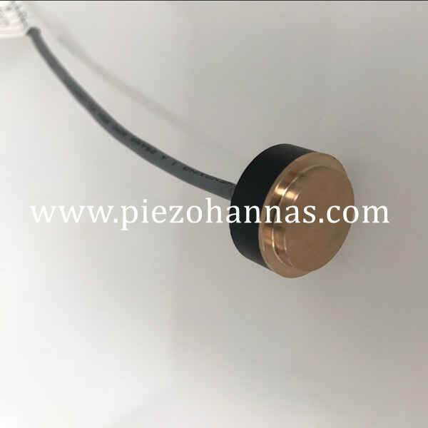
Dimensions:60x5mm Resonant frequency fr: 420 KHz±2% Electromechanical coupling coefficient K33:≥58% Resonant impedance Zm: ≤45 Ω Static capacitance Cs: 5100pF±14%@1kHz Application: Piezo transducer for milk analysis, Piezo transducer for vibration, transducer for matter dispersion, sonar transducer Ultrasonic sensor, vibration sensor, wall thickness sensor, material stress sensor, pressure sensor, energy electricity harvesting, compression sensor, piezo expansion sensor and others.
-
We can offer 2Mhz,4Mhz,6Mhz TCD Doppler Sensor .The shape of shell can be customized based on your requirements. Application:This probe is used for craniocervical doppler flowmeter,it is good anti-interference ability and high sensitivity,which has been integrated with many TCD equipment manufacturer.
-
We can offer the 5Mhz,8Mhz,10Mhz,13Mhz a-ultrasound sensor Application : The sensor used for measuring thickness of fat of Pet or livestock, and measuring distance or measuring thickness in ophthalmology.
-
Dimension: Outer Dimension: 18mm Inter Dimension: 15mm Height: 15mm Features of piezoelectric crystal: 1. Low impedance 2. The waveform is stable 3. High electromechanical conversion efficiency 4. Low dielectric loss 5. Heat a small 6. Big spray volume 7. The life of more than 5000 hours 8. Acid corrosion
-
Dimension : OD60mm xID30mm x Thi10mm For ultrasonic welding machine,our clients often order 60 x30 x10mm,50 x20 x6.5mm piezo ring ,they are in stock all in our factory. Please contact us as soon if any requirements.
-
Dimension : OD50mm xID20mm x Thi6.5mm For ultrasonic welding machine,our clients often order 60 x30 x10mm,50 x20 x6.5mm piezo ring ,they are in stock all in our factory. Please contact us as soon if any requirements.
-
Hemisphere piezo: Dimension: Diameter : 50mm OD of Hole:8mm Wall thickness : 2mm Features of high temperature piezoceramic: 1. Low impedance 2. The waveform is stable 3. High electromechanical conversion efficiency 4. Low dielectric loss 5. Heat a small 6. Big spray volume 7. The life of more than 5000 hours 8. Acid corrosion
-
Dimension (diameter×thickness):10mmx2mm Features of piezoelectric crystal: 1. Low impedance 2. The waveform is stable 3. High electromechanical conversion efficiency 4. Low dielectric loss 5. Heat a small 6. Big spray volume 7. The life of more than 5000 hours 8. Acid corrosion
-
Dimension (diameter×thickness):16mmx0.4mm Features of piezoelectric crystal: 1. Low impedance 2. The waveform is stable 3. High electromechanical conversion efficiency 4. Low dielectric loss 5. Heat a small 6. Big spray volume 7. The life of more than 5000 hours 8. Acid corrosion
-
Hemisphere piezo: Dimension: Diameter : 15mm OD of Hole:4mm Wall thickness : 1mm Features of high temperature piezoceramic: 1. Low impedance 2. The waveform is stable 3. High electromechanical conversion efficiency 4. Low dielectric loss 5. Heat a small 6. Big spray volume 7. The life of more than 5000 hours 8. Acid corrosion
-
About ultrasonic distance transducer, we can offer transducer that can detect 1M,3M,4M,5M,8M,12M,20M,30M,50M, Also we can accpet customization.
-
About ultrasonic distance transducer, we can offer transducer that can detect 1M,3M,4M,5M,8M,12M,20M,30M,50M, Also we can accpet customization.
-
Size: 54.5x47x40mm Application: Underwater communication device, Hydrophone , Sonar.


 Tech Co,.Ltd")


