Hubei Hannas Tech Co.,Ltd-Professional Piezoceramic Elements Supplier
Hot Keywords:
- All
- Product Name
- Product Keyword
- Product Model
- Product Summary
- Product Description
- Multi Field Search

Views: 0 Author: Site Editor Publish Time: 2026-07-31 Origin: Site


In underwater acoustics, the reliability of a sonar system or hydrophone array hinges directly on the precision, material stability, and geometric accuracy of its transducer components. Selecting the wrong dimension or material grade for piezoelectric elements leads to immediate field failures. Mismatched resonant frequencies ruin signal clarity. Degraded sensitivity under severe hydrostatic pressure blinds your passive arrays. Premature depolarization in deep-water deployments causes complete system shutdowns.
You face strict boundaries when moving from prototyping to full-scale production. Navigating the exact trade-offs between geometry, frequency, and ceramic formulation is critical. You must ensure optimal acoustic performance alongside long-term deployment viability. We explore how exact diameter measurements dictate operational bandwidth. We also examine why material choices divide sharply between active transmitters and passive receivers. Understanding these engineering constraints guarantees you build robust, field-reliable equipment.
Shape dictates performance: Piezo tubes provide superior omnidirectional radial acoustics compared to discs or rings, making them the industry standard for hydrophones and towed arrays.
Size and frequency are inversely linked: A tube’s mean diameter primarily dictates its radial (hoop) resonant frequency; precise dimensional tolerances are non-negotiable.
Material matching is application-specific: Hard piezo ceramics (like PZT-4/PZT-8) are engineered for high-power transmitting sonar, while soft ceramics (like PZT-5A) deliver the high sensitivity required for passive listening devices.
Environmental resilience requires upfront specification: Hydrostatic pressure in deep-water environments demands specific wall-thickness ratios and robust electrode configurations to prevent mechanical failure or performance drift.
Towed sonar arrays, sonobuoys, and autonomous underwater vehicles (AUVs) require 360-degree acoustic fields. Engineers face highly constrained payload spaces inside these devices. You cannot easily fit bulky directional projectors into a sleek AUV hull. Every successful Underwater Acoustic Transducer relies heavily on optimizing component geometry to solve this packaging problem.
When evaluating shapes, engineers consistently choose cylindrical tubes over flat discs or solid rings. Tubes excel at generating superior radial vibration modes. This means they expand and contract outward, producing an omnidirectional sound radiation pattern. Discs primarily vibrate thickness-wise, creating narrow, directional acoustic beams. While directional beams work well for depth sounders, they fail in systems needing full-circle coverage.
You will find these cylindrical components playing dual roles across many Applications of underwater communications. In active sonar, they emit strong acoustic "pings" radially into the water column. In passive systems, they listen continuously, capturing faint acoustic signatures from distant targets.
To declare a design successful, a specified tube must maximize specific hydrostatic strain coefficients. These coefficients determine overall acoustic efficiency:
Hydrostatic strain constant ($d_h$): Measures the physical displacement per unit of applied voltage. Higher values mean better transmission power.
Hydrostatic voltage constant ($g_h$): Measures the voltage generated per unit of applied acoustic pressure. Higher values indicate excellent receiver sensitivity.
Balancing these two constants while maintaining structural integrity within the housing remains the primary challenge for acoustic engineers.
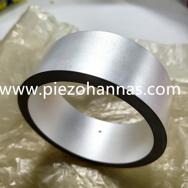
Physical dimensions strictly dictate acoustic limits. You cannot separate a component's geometry from its operational frequency band. Understanding this relationship helps you engineer the exact acoustic window required for your deployment scenario.
The most critical dimension is the mean diameter. The mean diameter shares an inverse relationship with the radial (hoop) resonant frequency. The acoustic wave travels circumferentially around the cylinder. Therefore, larger tubes create lower frequency resonance. Low-frequency sound waves travel much further underwater, making large tubes ideal for deep-ocean penetration and long-range detection. Conversely, smaller tubes generate high-frequency resonance. High-frequency signals attenuate quickly but provide exceptional resolution, making small tubes perfect for short-range seafloor mapping or obstacle avoidance.
Wall thickness introduces another layer of complex trade-offs. You must balance electrical properties against mechanical survival.
Thicker walls: They dramatically increase mechanical strength against crushing hydrostatic pressure. However, increasing wall thickness reduces the component's electrical capacitance. Lower capacitance forces your driving electronics to supply higher voltages to achieve the same acoustic output.
Thinner walls: They offer higher capacitance, broader bandwidth, and superior sensitivity. Your system requires less driving voltage. Unfortunately, thin walls introduce severe structural fragility, risking implosion in deep-water environments.
Finally, you must consider the overall length. The length strictly governs longitudinal resonance. A common engineering mistake involves designing a cylinder where the longitudinal resonant frequency overlaps the radial resonant frequency. This overlap causes destructive acoustic interference. To prevent this, you must deliberately decouple the length modes from the radial modes. Keeping an aspect ratio (length to diameter) either distinctly large or distinctly small ensures clean, predictable acoustic performance.
Dimension Adjustment | Primary Acoustic Effect | Trade-off / Risk |
|---|---|---|
Increase Mean Diameter | Lowers radial resonant frequency | Requires larger payload housing |
Decrease Mean Diameter | Raises radial resonant frequency | Reduces signal penetration depth |
Increase Wall Thickness | Improves deep-water pressure resistance | Lowers capacitance; needs higher drive voltage |
Decrease Wall Thickness | Increases sensitivity and bandwidth | High risk of mechanical crushing at depth |
You must categorize Lead Zirconate Titanate (PZT) grades strictly by their intended end-use. Piezoelectric material selection is a rigid engineering trade-off. No single formulation excels at both high-power transmission and maximum passive sensitivity.
Industry standards often group these materials into "Hard" and "Soft" categories. These terms do not describe physical hardness. Instead, they describe the material's internal domain mobility and resistance to depolarization.
Commonly designated as Navy Type I and Navy Type III, hard piezo ceramics are engineered for active sonar transmitters and high-power underwater projectors. They endure extreme electrical driving forces without degrading.
Hard materials exhibit exceptionally low dielectric loss. When you drive them continuously with high voltages, they generate very little internal heat. They also possess a high mechanical quality factor ($Q_m$), meaning they ring sharply at their resonant frequency. Most importantly, they resist depolarization under high mechanical stress and extreme electrical drive levels. If your system requires projecting loud acoustic pings across miles of ocean, you must select a hard ceramic formulation.
Designated as Navy Type II and Navy Type VI, soft piezo ceramics dominate the passive listening space. You will find them inside hydrophones, towed array receivers, and passive acoustic monitors.
Soft materials prioritize extreme sensitivity. They feature exceptionally high piezoelectric constants ($d_{31}$, $g_{31}$). They easily convert the faintest acoustic pressure wave into a measurable electrical signal. However, this sensitivity comes at a steep cost. If you drive a soft ceramic with high transmission power, its high dielectric loss causes rapid internal heating. This heat, combined with the material's highly mobile internal domains, quickly leads to irreversible depolarization. Once depolarized, the component becomes entirely useless.
Material Category | Common Grades | Navy Designation | Best Application | Key Characteristic |
|---|---|---|---|---|
Hard Ceramics | PZT-4, PZT-8 | Type I, Type III | Active Transmitters, Projectors | Low dielectric loss, high power handling |
Soft Ceramics | PZT-5A, PZT-5H | Type II, Type VI | Passive Receivers, Hydrophones | High sensitivity, high piezoelectric constants |
The ocean remains a uniquely hostile operating environment. You must address the physical limits of piezo ceramic tubes for sonar long before deployment. Laboratory bench testing rarely accounts for the compounding stresses found at crushing oceanic depths.
Depth fundamentally alters material behavior. As an AUV or towed array descends, static hydrostatic pressure increases exponentially. This pressure compresses the ceramic crystal lattice. At extreme depths, this static compression significantly alters the piezoelectric charge constant. Your system might perform perfectly at a depth of 10 meters, but lose half its sensitivity at 1,000 meters. You must calculate the operational depth limit mathematically to prevent mechanical crushing and ensure your wall thickness provides an adequate safety margin.
Depolarization poses another silent threat. Extreme temperature fluctuations severely impact ceramic longevity. A sonar system might sit in a sun-baked shipping container at 40°C, only to plunge into 2°C Arctic waters hours later. This thermal shock, combined with continuous mechanical stress over months of deployment, degrades the internal polarization of soft ceramics. You must specify pre-aging treatments during manufacturing to stabilize the material before potting.
Electrode and coating durability determine the ultimate lifespan of the assembly. Manufacturers typically provide two main electroding options:
Fired-on Silver: The industry standard. It offers excellent conductivity and cost-effectiveness. However, silver is susceptible to migration and oxidation if exposed to moisture.
Electroless Nickel: Preferred for harsh environments. Nickel offers superior corrosion resistance and better solderability. It bonds more reliably when hermetically sealed in oil-filled arrays or encapsulated within rigid polyurethane-potted assemblies.
Selecting the right electrode finish prevents premature joint failure caused by the constant flexing and vibration typical in marine deployments.
Transitioning from a working prototype to bulk production requires rigorous supplier auditing. Procurement and engineering teams must evaluate manufacturers based strictly on their precision capabilities and quality control documentation.
Demanding strict tolerances on precision machining is non-negotiable. Even microscopic variations in concentricity, outer diameter (OD), or inner diameter (ID) will shift the resonant frequency. If a manufacturer delivers a batch of components with loose dimensional tolerances, your fully assembled array will suffer from severe frequency drift. One hydrophone might peak at 25 kHz, while its neighbor peaks at 28 kHz. This inconsistency destroys the beamforming capabilities of modern phased arrays.
You also need to audit a vendor's customization capabilities. Standard silver-coated cylinders rarely meet the needs of advanced military or commercial sonar designs. You should look for vendors who offer custom electrode patterning. For example, striped electrodes allow you to utilize a single cylinder as a multi-element phased array. Furthermore, you must ensure the vendor can execute custom polarization directions. While radial polarization is standard, some specialized transducer architectures require longitudinal or tangential polarization to excite specific acoustic modes.
Take concrete next steps before committing to bulk orders. First, request small sample batches manufactured to your exact dimensional prints. Subject these samples to rigorous acceptance testing. Perform impedance analyzer sweeps to verify that resonant frequencies, anti-resonant frequencies, and capacitance fall within your specified tolerances. Finally, encapsulate these prototypes in your chosen polyurethane or oil-filled housing and validate them inside pressurized acoustic test tanks. Only authorize full-scale production once the assembly survives simulated deployment depths.
Sourcing Piezo Tubes for sonar requires a rigid alignment of geometric sizing, resonant frequency targets, and material properties. You cannot separate the physical dimensions from the acoustic outputs, nor can you ignore the strict boundaries between hard and soft PZT formulations.
We strongly recommend prioritizing manufacturers who provide transparent testing data and guarantee tight concentricity tolerances. You must match the specific material grade to your exact application, balancing transmission power needs against passive sensitivity requirements and depth survival metrics.
Prompt your engineering team to review your current hydrophone or sonar transducer schematics today. Identify your critical frequency limits and hydrostatic pressure constraints, then request a detailed technical spec sheet for custom piezo tube manufacturing to ensure your next deployment succeeds flawlessly.
A: Soft ceramics like PZT-5A are highly recommended for deep-water hydrophones. They provide exceptionally high sensitivity and maintain excellent stability across fluctuating ocean temperatures. However, you must ensure the engineered wall thickness can adequately support the extreme hydrostatic pressure found at deployment depths to prevent mechanical crushing.
A: The resonant frequency is governed primarily by the specific frequency constant of the chosen material divided by a key physical dimension. For the common radial (hoop) mode, you divide the frequency constant by the mean diameter. For the longitudinal mode, you divide it by the tube's length.
A: Yes, they can operate as both transmitters and receivers. However, this dual functionality requires a compromise material, typically a specifically tuned grade of PZT-4. It also demands careful tuning of your drive electronics, as materials optimized for sensitive receiving differ fundamentally from those built for high-power transmitting.
A: Fired-on silver is the standard, most cost-effective option for typical applications. Electroless Nickel or Gold is strongly preferred for harsher deployment environments. These premium metals provide superior corrosion resistance and support highly reliable soldering and bonding processes inside complex, oil-filled or potted underwater transducer assemblies.