Hubei Hannas Tech Co.,Ltd-Professional Piezoceramic Elements Supplier
Hot Keywords:
- All
- Product Name
- Product Keyword
- Product Model
- Product Summary
- Product Description
- Multi Field Search

 |


| Quantity: | |
|---|---|
PHA-200-01KF
Piezohannas
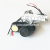
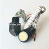
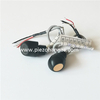
PHA-200-01KF
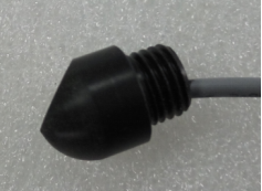
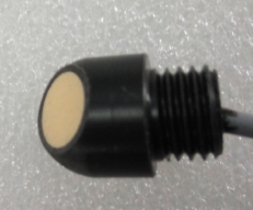
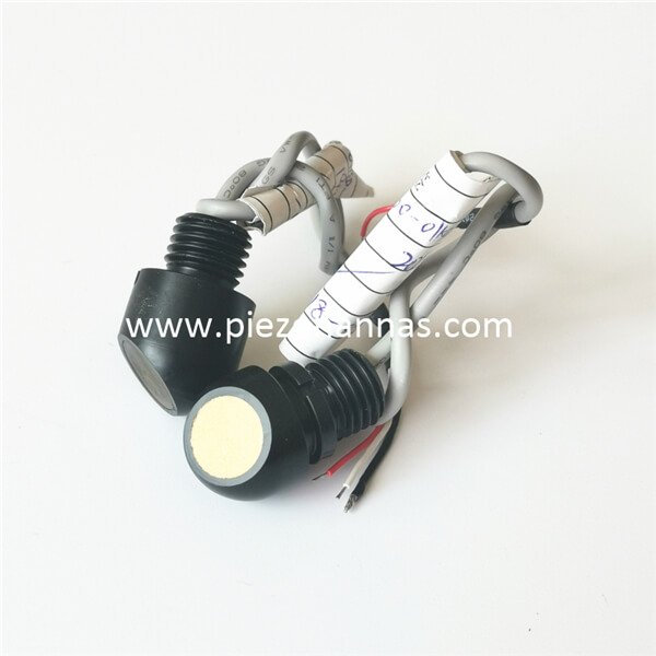
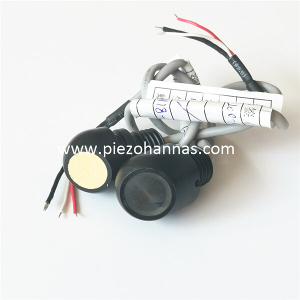
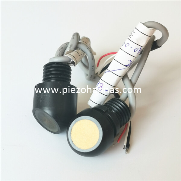
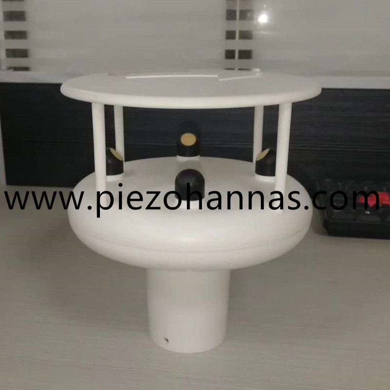
200KHz Ultrasonic Transducer Ultrasonic Wind Transducer for Weather Stations
Technical parameters:
Items | Technical Parameters | Image | |
Name | 200KHz ultrasonic transducer |
| |
Model | PHA-200-01KF | ||
Frequency | 200KHz±5% | ||
Detection Distance | 0.10~1.5m | ||
Minimum Parallel lmpedance | 455Ω±20% | ||
1410pF±20% @1KHz | |||
Sensitivity | Driving Voltage:800Vpp,Distance:0.3m, Echo Amplitude:30mV | ||
-40~+80℃ | |||
≤3Kilos or 0.3MPa | |||
| (Beamwidth) Half-power Beam Width@-3dB:10°±10%, Sharp Angle:24°±10% | ||
Housing Material | POM | ||
Usage | anemorumbometer,ultrasonic gas flowmeter | ||
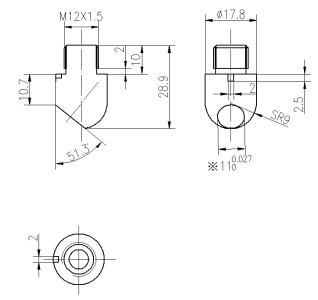
thread:M12*1.5 | |||
Protection Level | IP68 | ||
Weight | 10g±5%(Length:25cm) | ||
Wiring Instructions | integrated type:connector:Red+,White-,Black: shielded wire; | ||
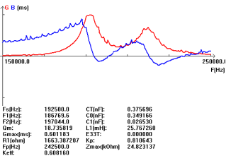
Admittance Curve | Product Structure Diagram | ||
|
| ||
Block diagram of ultrasonic distance transducer :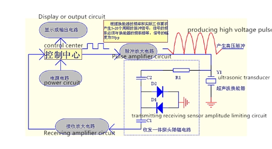
Schematic Diagram of Temperature Sensor (model: MF58_502F3470):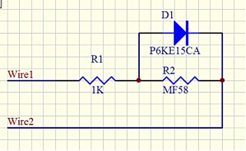
Integrated type Cable instruction:
1.Wiring instruction of transducer: interface (3pin, 2.54mm terminal)
Red: transducer +
White: transducer -
Black: shielding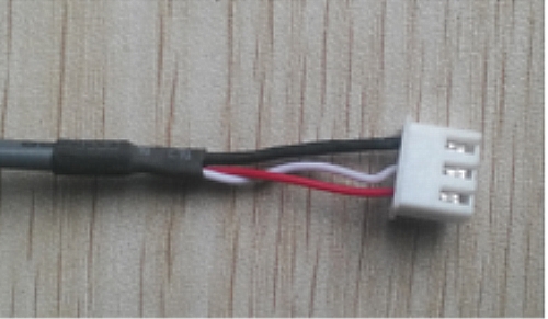
2.Cable Instruction of Temperature Sensor: interface (3pin, 2.0mm terminal)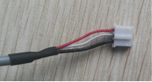
Red and black are temperature sensor wiring
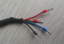
Split type: standard 10m cable, with each additional 50m of cable, the signal attenuation is 6dB
Three-core wiring instructions:
Red: Transducer +
Blue: temperature sensor +
Black: Public-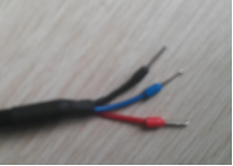
Four-core wiring instructions:
Red: Transducer +
Yellow: Transducer-
Blue, black: temperature sensor
A typical ultrasonic anemometer consists of 2 pairs of ultrasonic transducers mounted at right angles to one another as shown in the figure below. Each sensor is capable to transmit and receive ultrasonic pulses. The physical distance between the opposite facing sensors is fixed and known. During operation, the time taken for an ultrasonic pulse of sound to travel from the North (N) transducer to the South (S) transducer is compared to the time for a pulse to travel from S to N transducer. If there were no wind blowing, the two times should exactly match. Otherwise, the sound wave traveling with the wind should arrive earlier than the sound traveling against it. For example, if there is a wind blowing to N, the N to S travel time would be more compared to the S to N travel time. The difference in the time of flight can give the relative speed of wind along NS axis. Similarly, flight times are also compared along the East-West and West-East directions to compute the wind velocity along the EW axis. The two rectangular velocity components of the wind are then combined to compute the wind vector with a resultant sum and an angle of wind velocity. The sensor arrangement shown below gives only the horizontal wind speed. Measuring a three dimensional wind speed requires sensor arrangements along the vertical direction too.
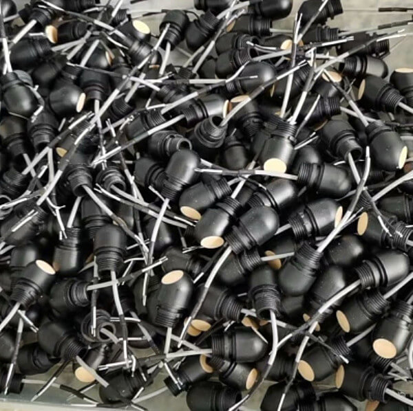
Application Image :


 Tech Co,.Ltd")