Hubei Hannas Tech Co.,Ltd-Professional Piezoceramic Elements Supplier
News
You are here: Home / News / Ultrasonic Transducer information / What’s the ultrasonic ranging module transducer

What’s the ultrasonic ranging module transducer

Views: 5     Author: Site Editor     Publish Time: 2018-09-17      Origin: Site

Inquire

facebook sharing button
twitter sharing button
line sharing button
wechat sharing button
linkedin sharing button
pinterest sharing button
whatsapp sharing button
sharethis sharing button

The main purpose of ultrasonic transducers is to measurement and alarm. The design involves more content, mainly combining the single-chip control module, ultrasonic ranging module, buzzer alarm module and 4-digit digital tube display module. The core of this design is the ultrasonic ranging module. Other related modules are expanded on the basis of ranging. The ranging module uses ultrasonic sensors, and then selects the appropriate single-chip microcomputer. The following is discussed from relevant aspects. Ultrasonic range finder is an ultrasonic wave that is beyond the limits of human hearing, that is, a mechanical wave whose vibration frequency is higher than 20 kHz. When the ultrasonic sensor is working, the voltage and the ultrasonic wave are mutually converted. When the ultrasonic sensor transmits the ultrasonic wave, the ultrasonic wave transmitting probe emits the ultrasonic wave converted by the voltage. When is receiving the ultrasonic wave, the ultrasonic receiving probe sends the ultrasonic converted voltage back. Go to the microcontroller control chip. The ultrasonic wave has the advantages of high vibration frequency, short wavelength, small diffraction phenomenon and good directivity, and can also be directed to the reflection line, and the energy consumption of the ultrasonic sensor is slow to facilitate the distance measurement. In the medium and long distance measurement, the accuracy and directivity of the ultrasonic sensor are much better than the infrared sensor, but the price is also slightly more expensive. From the aspects of safety, cost and directionality, ultrasonic sensors are more suitable for design requirements.


The system selects 52 single-chip microcomputers as the core of the control system. The value of ultrasonic transducer for distance is displayed by the 4-digit common cathode digital tube. The different distances between the obstacles use the different alarm sounds of the buzzer frequency, and the ultrasonic transmission signal is composed of 52 single-chip microcomputers. The P1.0 port is sent to the ultrasonic transmitting circuit to transmit the ultrasonic wave, and the alarm system is composed of a buzzer circuit. In this design, the probe that sends and receives ultrasonic waves is separated, so that the transmission and reception signals are not aliased, thereby avoiding interference, and the reliability of the system can be well improved. The system block diagram is as follows:


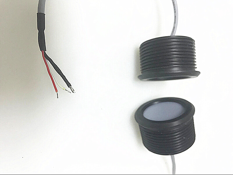
Ultrasonic ranging module


Module function, the module uses ultrasonic range finder to test the distance between the car and the obstacle. When the distance is less than a given value, the program is used to transmit the signal to a confirm pin of the MCU. Other control modules detect the level of the pin and control the driving state of the car according to the level.

The basic principle is that the ultrasonic ranging module can provide 2cm-400cm non-contact distance sensing function, the ranging accuracy can reach 3mm, and the module includes ultrasonic transmitter,receiver and control circuit. Basic working principle includes aspects:


1) Using IO port TRIG to trigger ranging, giving a high level signal is  at least 10us;
2) The module automatically sends 40khz square waves to automatically detect whether there is a signal return;
3) There is a signal return and output through the IO port ECHO, the high level duration is the time from the transmission to the return of the ultrasonic wave, the test distance = (high time * sound speed)


The display module of ultrasonic sensor for distance measurement is a digital tube divided into dynamic display and static display. Here, the dynamic display is selected, and the dynamic display driver: the digital tube dynamic display interface is one of the most widely used display modes in the single-chip microcomputer, and the common pole COM of each digital tube .The strobe control circuit is added, and the bit strobe is controlled by independent I/O lines. When the MCU outputs the glyph code, all the digital tubes receive the same glyph code, but the digital tube will display the glyph, depending on In the control of the single-chip strobe COM terminal circuit of the single-chip microcomputer, we only need to turn on the control of the digital tube to be displayed, and the bit will display the glyph, and the digital tube without the strobe will not light. By controlling the COM end of each digital tube in turn, the digital tubes are controlled to display in turn, which is dynamic driving. During the rotation display process, the lighting time of each digital tube is 1~2ms. Due to the persistence of human vision and the afterglow effect of the LED, although the digital tubes are not lit at the same time, as long as the scanning speed is sufficient fast, the impression is a stable set of display data, there will be no flickering, the dynamic display is the same as the static display, which can save a lot of O ports, and lower power consumption. The alarm module controls the buzzer's chime according to the distance displayed by the distance (using the I/O port to generate a square wave of frequency).The main functions of the software design system program design are to transmit ultrasonic waves, receive ultrasonic waves, calculate measurement distance, data calculation, buzzer alarm and digital tube display main program flow chart as above. When an interrupt occurs, interrupt processing will be performed. Design interrupt processing flow chart interrupt processing flow includes alarm processing and digital tube scanning processing.

What’s the ultrasonic ranging module transducer

Ultrasonic ranging error analysis, according to the principle of ultrasonic distance sensor, the sources of measurement error are: 1. The deviation between starting transmission and starting timing; 2. Receiving the echo to the detected lag; 3. Receiving the interruption to The lag between the interrupt response timing; 4, the error of the timer itself; 5, the effect of temperature on the sound wave speed above factors. The second error is due to the sensitivity and judgment bias of the detection circuit. There is definitely a hysteresis from the receipt of the actual echo to the circuit confirmation and output of the corresponding signal, which is related to the strength of the echo signal, the principle of the detection circuit and the sensitivity of the judgment circuit. It is also the core of ultrasonic ranging. Because if the sensitivity is too high, some interference signals will be mistaken as echoes, resulting in the measurement errors. If it is too low, the detection distance is greatly limited because the echo attenuation is the square of the distance. This part of the error is the main source of data instability, because the judgment lag will change with the strength of the echo.


Feedback
Hubei Hannas Tech Co.,Ltd  is a professional piezoelectric ceramics and ultrasonic transducer manufacturer, dedicated to ultrasonic technology and industrial applications.                                    
 

RECOMMEND

CONTACT US

Add: No.302 Innovation Agglomeration Zone, Chibi Avenu ,Chibi City, Xianning, Hubei Province,China
E-mail: sales@piezohannas.com
Tel: +86 07155272177
Phone: +86 +18986196674         
QQ: 1553242848 
Skype: live:mary_14398
​        
Copyright 2017  Hubei Hannas Tech Co.,Ltd All rights reserved. 
Products