Hubei Hannas Tech Co.,Ltd-Professional Piezoceramic Elements Supplier
Hot Keywords:
- All
- Product Name
- Product Keyword
- Product Model
- Product Summary
- Product Description
- Multi Field Search

Views: 5 Author: Site Editor Publish Time: 2021-05-18 Origin: Site


Acoustic waves are considered to be the only information carrier that can travel long distances in the ocean. Marine research, resource development, and maritime military struggles are all inseparable from underwater acoustic technology. The development of hydroacoustic technology requires various types of hydroacoustic transducers to provide support, and the mission of hydroacoustic transducers is to transmit and receive sound waves underwater, so hydroacoustic transducers are known as the “eyes and ears of hydroacoustic equipment.The development of hydroacoustic transducers mainly includes the application of new materials, the adoption of new processes, and the design of new structures to achieve the improvement and enhancement of the comprehensive technical performance of the transducer. The urgent demand from the field of hydroacoustic technology is the direct development of hydroacoustic transducers. power. This article focuses on the domestic research results of underwater acoustic transducers in the past 20 years, mainly including new developments in low-frequency transducers, high-frequency broadband transducers, deep-water transducers, and vector hydrophones. Based on the analysis and summary, combined with my country's marine technology development strategy and situation, briefly discuss the challenges and development opportunities faced by the current underwater acoustic transducer technology.
The underwater acoustic transducer is a type of sensor that realizes the conversion of sound and other forms of energy or information in the water medium; the underwater acoustic transducer is the front-end equipment of the sonar system, and it is also the interaction between the sonar system and the water medium to exchange information. window". The field of research and development of underwater acoustic transducer technology involves the integration of multiple disciplines, and the closely related disciplines mainly include: physics, materials science, mathematics, mechanics, electronics, chemistry, mechanics, etc., so the development of underwater acoustic transducers It is closely related to the achievements of other basic disciplines, and at the same time is restricted by the development of various related disciplines. Judging from the decades of development history of my country's hydroacoustic transducers, the biggest development motivation comes from the application requirements in the field of hydroacoustic technology, but until the end of the 20th century, the development of my country's hydroacoustic transducer technology lacked overall and systematic nature.
1.1 Research progress of low-frequency transducers
In response to the urgent needs of ultra-long-range underwater information transmission and the development of ultra-stealth submarine detection, low-frequency transmitting transducers have become one of the most concerned hotspots in the field of underwater acoustic transducers since the 21st century. The working frequency band of foreign ultra-long-range detection and communication sonar Has been reduced to about 100 Hz. Low-frequency transducers involve many theoretical and technical problems, which have not been solved well at present, and this aspect will still be the research hotspot and focus of attention in the future development. This section selects the research work of flexural vibration low-frequency transducers and flexural-tension transducers, and summarizes the new technological achievements.
1.1.1 Bending vibration low-frequency transducer
The first technical problem faced by the development of low-frequency underwater transducers is the geometric size. Generally, the working frequency of resonant transducers is inversely proportional to the geometric size. That is to say, the lower the frequency of the transducer, the larger the geometric size will be. Vibration can effectively reduce the geometric size of low-frequency transducers. The new designs of low-frequency flexural vibration transducers in China in the past 20 years mainly include curved beam transducers and curved disc transducers.
(1) Bending beam transducer. Design a cylindrical cantilever beam broadband transmitter transducer (Figure 1a). The structure design combines the characteristics of low flexural vibration modal frequency and the method of multi-modal vibration coupling to broaden the frequency band. Chai Yong et al. It is proposed a tube-beam coupling ring transducer (Figure 1b). By adding a curved beam to the inlaid ring-shaped transducer to form a tube-beam coupling structure, the effective working mode is increased. Use multi-mode coupling to achieve low-frequency and wide-band operating characteristics. The overflow structure is adopted, and its ability to withstand hydrostatic pressure has been verified by the actual application of the 3 000 m deep-sea submersible standard. Xu et al. proposed two design schemes for cylindrical low frequency transducers (Figure 1c and d), conducted a series of simulations, and gave the emission response curves driven by the new magnetostrictive materials Terfenol-D and Galfenol. It demonstrates the potential of the transducer structure for ultra-low frequency applications.
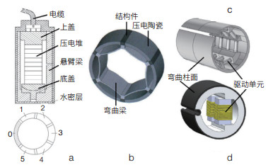
Figure 1 New design of low-frequency transducer for curved beam (a), 0 is a fixed beam, and 1-5 are cylindrical beams with different thicknesses |
(3) Bent disk transducer. The curved disc transducer includes three-stack, double-stack structures and so on. Figure 2a shows a compact curved disc transducer composed of a pair of double laminations. The foreign research work is relatively mature. It is conducted in-depth research on this basic structure of the curved disc transducer. Starting from this basic structure, by designing the liquid chamber and improving the driving mode, some new designs have been produced]. Figure 2b is a curved disc transducer driven by a mosaic ring. The design of Figure 2c uses curved disk transducers of different sizes to form a matrix, and uses different driving methods to achieve broadband operation. Figure 2d is a curved disc transducer with overflow cavity structure. The size of the liquid cavity is appropriately adjusted in the design to meet the acoustic performance requirements. It is a curved disc transducer driven by galfenol, which uses a structure similar to a longitudinal transducer to excite the bending vibration of the front radiating
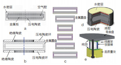
Figure 2 New design of low-frequency transducer with curved disc
1.1.2 Flextensional transducer
The concept of the flextensional transducer started from Hayes' patent in 1936. The basic working mode is that one or more telescopic vibrators drive the flexural vibration shell to generate low-frequency sound radiation. The research and application of flextensional transducers in my country has been active since the end of the 20th century. Researchers have designed flextensional transducers with various structures. According to the structure and excitation method, the flextensional transducers are divided into three categories. This classification method is used here to introduce separately.
(2) Bending-tension transducer with cylindrical structure. This type of transducer is driven by a longitudinal telescopic vibrator to translate the flexural vibration shell. The vibrating shell of the transducer is a translational structure, that is, a cylindrical shell of various shapes, which is driven by one or more longitudinal telescopic vibrators. Including IV type flextensional transducer and its deformation structure, VII type flextensional transducer, quadrilateral flextensional transducer, etc. Figure 3a is a typical IV type flextensional transducer structure. The IV type flextensional transducer driven by a relaxor ferroelectric single crystal PMNT material has been developed. The IV type flextensional transducer driven by the rare earth giant magnetostrictive material Terfenol-D was developed. Figure 3b is the new design of the VII type flextensional transducer, which is driven by the rare earth giant magnetostrictive material Terfenol-D. The excitation method is designed at the widest part of the transverse dimension, and a pair of parallel vibrators are designed to give an in-depth look at this type of transducer. The series of researches include prestress design analysis, theoretical modeling, modal analysis, experimental research, etc. Figure 3c is an improved new design of the IV type flextensional transducer, which is similar to the design improvement of the type I flextensional transducer to the type II flextensional transducer, using an elliptical shell structure with an elongated long axis, the transducer It is driven by the relaxor ferroelectric single crystal material PMNT, which has better broadband operating characteristics than the general IV type flextensional transducer. Figure 3d is the earliest new design to improve the IV type flextensional transducer in China-the fish-lip type flextensional transducer , which uses a variable height elliptical shell and uses the rare earth super magnetostrictive material Terfenol- D drive, this special-shaped vibrating shell has a lever arm effect and a highly weighted double-amplification effect. At present, the Terfenol-D fish-lip flextensional transducer has been serialized and designed into a double-shell structure to further increase the transmission power. The maximum sound power of a single transducer can reach 10,000 watts, making it a domestic low-frequency high-power transmitting transducer One of the basic types. Figure 3e is an orthogonal excitation quadrilateral flextensional transducer, which adopts a compact design improvement, which can add more functional materials in a limited volume and improve the emission sound source level. Figure 3f is another improved new design of the IV type flextensional transducer, similar to the design improvement of the type I flextensional transducer to the type III flextensional transducer, which uses two elliptical shells in series along the long axis direction As a whole, a longer piezoelectric stack is used to excite, so that the resonance frequency of the longitudinal vibrator is reduced and close to the fundamental frequency mode of the flexural shell, which is conducive to modal coupling to achieve broadband operating characteristics. Figure 3g is an improved new design for the excitation vibrator of the IV type flextensional transducer. It is an IV type flextensional transducer driven by the folding vibrator. This structure combined with a low-rigidity housing material can effectively reduce the resonance frequency.
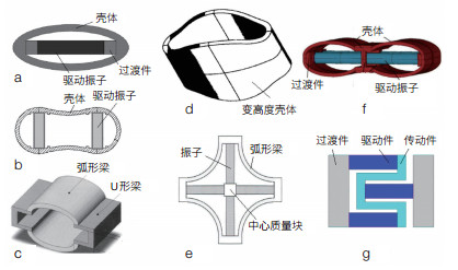
Figure 3 Bending-tension transducer with column structure
It is also known as the gourd type flextensional transducer. It is studied the gourd type flextensional transducer driven by PZT and PZT+Terfenol-D. , The simulation analysis of the emission characteristic parameters of the joint excitation is carried out. Figure 4c is a concave-tube flex-tension transducer excited by magnetostriction-piezoelectric combination. In the design, two excitation elements, Terfenol-D and PZT, are used to form a composite longitudinal vibrator. Figure 4d shows the concave-cylinder flextensional transducer.it is excited by the multi-piezoelectric stack. Under the premise that the shell remains unchanged and the total volume of the piezoelectric ceramic material is the same, the analysis of different numbers (1-4) piezoelectric stack drives For the impact on the performance of the transducer, a concave-tube flexural-tension transducer excited by a triple piezoelectric stack was designed and developed.
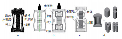
Figure 4 Long-type rotating body bending-tension transducer
Flat-type rotating body bending-tension transducer. This type of transducer is driven by a radially expanding vibrator to drive a rotationally symmetrical bending vibration shell. The vibrating shell of the transducer is a rotationally symmetrical structure, generally a pair of convex or concave spherical caps (or spherical caps) or It is composed of a disc, etc., driven by a radially expanding ring or disc vibrator, including V-shaped flex-tension transducer, VI-shaped flex-tension transducer, disc-shaped flex-tension transducer, etc., introduced here Small size V-type flextensional transducer-Cymbal and disc type flextensional transducer . Figure 5a is a small-size V-shaped flextensional transducer. A pair of metal end caps are driven by a piezoelectric ceramic disc that vibrates radially to produce flexural vibration; Figure 5b is a disc-shaped flextensional transducer, which uses PZT- in the design. 4 The radially polarized piezoelectric ceramic ring drives the curved disc. The disc is divided into 16 equal sectors along the radial slit to reduce the coupling of lateral vibration. The flextensional transducers of these two structural forms have the characteristics of low resonant frequency, small geometric size, and high electroacoustic efficiency.
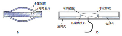
Figure 5 Flat-type rotating body bending-tension transducer
1.2 Research progress of high-frequency broadband transducers
In addition to the detection distance as an important indicator of underwater acoustic equipment, another development direction is to obtain the maximum amount of target information as the main purpose. For example, high-resolution image sonar, high-data-rate underwater acoustic communication, etc. It require high-frequency mode operation, and the working frequency band is as wide as possible. Therefore, high-frequency broadband underwater acoustic transducer has become a key component of the system, similar to optics. The lens of the imaging system is the same.
Figure 6a is a high-frequency broadband transducer with piezoelectric ceramic column and matching layer. The ratio of piezoelectric ceramic spacing to ceramic size and the effect of filling materials on the bandwidth are studied. The double matching layer high frequency broadband transducer designed in Figure 6b uses piezoelectric ceramic columns to form an array, and then adds a double matching layer structure of metal layer and resin composite material to achieve high frequency broadband acoustic emission performance. Figure 6c shows the designed 1-1-3 piezoelectric composite high-frequency broadband transducer, which consists of 1-dimensional connected piezoelectric pillars and 1-dimensional connected metal pillars arranged in parallel in a 3-dimensional connected polymer matrix. The three-phase piezoelectric composite material is formed, and the high-frequency broadband transmitting transducer has been developed. Figure 6d shows the designed 1-3 piezoelectric composite high-frequency broadband transducer, which uses the coupling effect of the thickness vibration mode and the first-order transverse vibration mode to realize the broadband operating characteristics. Figure 6e shows the designed piezoelectric composite ring high-frequency broadband transducer. The piezoelectric composite ring is obtained by radially cutting the piezoelectric ceramic ring and pouring epoxy resin. Then, two piezoelectric composite rings with different wall thicknesses are obtained. The composite ring is superimposed to form a radially radiating dual-resonant transducer.
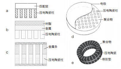
Figure 6 High-frequency broadband transducer
 Tech Co,.Ltd")


