Hubei Hannas Tech Co.,Ltd-Professional Piezoceramic Elements Supplier
Hot Keywords:
- All
- Product Name
- Product Keyword
- Product Model
- Product Summary
- Product Description
- Multi Field Search

Views: 0 Author: Site Editor Publish Time: 2026-09-09 Origin: Site


Standardizing dimensions alone is never enough for successful piezoelectric integration. The true electromechanical response depends entirely on how the internal crystal domains align within the material. Without this precise alignment, even the most accurately machined ceramic will fail to deliver the expected mechanical output.
Often, incorrect specification of the poling axis creates severe downstream issues. Engineers face sub-optimal displacement, unintended shear forces, or even premature depolarization under heavy load. These errors cost both time and budget during product assembly.
For engineers and procurement teams transitioning from prototyping to large-scale scale, clarity is absolutely essential. Defining the exact polarization setup alongside the electrode layout is critical for ensuring repeatable performance and mitigating assembly risks. In this article, you will discover how polarization dictates displacement modes, influences material parameters, and drives component geometry. We will also cover real-world failure modes and provide a practical procurement checklist.
The polarization axis strictly dictates the primary deformation mode (longitudinal, transverse, or shear).
Every PZT Material Parameter (like d33, d31, d15) is directly referenced against the established poling direction.
Component geometry dictates manufacturability: Piezo Plates and Blocks handle thickness/length expansion differently than radial expansion in Piezo Tubes.
Evaluating operational limits against the polarization axis (thermal, electrical, and mechanical stress) prevents in-field depolarization failures.
Before selecting a specific ceramic formulation, we must define the industry-standard coordinate system used worldwide. In the realm of piezoceramics, Axis 3 universally represents the primary poling direction. You use this axis as the fundamental baseline to measure every other directional property and electromechanical response. When you evaluate a PZT Material Parameter, you are essentially looking at how the ceramic structure responds relative to this critical Axis 3.
Let us carefully map specific d-coefficients (piezoelectric charge constants) to their physical performance outcomes. The interaction between the electrical field and the polarization axis yields distinctly different mechanical behaviors:
d33 (Longitudinal): In this mode, the electric field runs exactly parallel to the established polarization. This configuration delivers the highest possible force output but generally produces a relatively short displacement stroke. It serves as the powerhouse mode for stiff environments.
d31 (Transverse): Here, the electric field operates orthogonally to the primary mechanical strain. You typically use this parameter to evaluate bending motions in flat actuators.
d15 (Shear): For this mode, you apply the electric field perpendicular to the original polarization axis. This creates a sliding or shearing action across the face of the ceramic, rather than a direct push or pull.
Prioritizing one specific parameter often forces unavoidable structural trade-offs in component rigidity and mounting complexity. If you want maximum compressive force, you need a thicker, more rigid component. This inherently increases your mounting complexity and requires stiffer surrounding mechanics. Conversely, choosing the transverse effect gives you much larger deflection capabilities but sacrifices overall system rigidity. You must weigh these factors carefully to balance force generation against acceptable deflection limits.
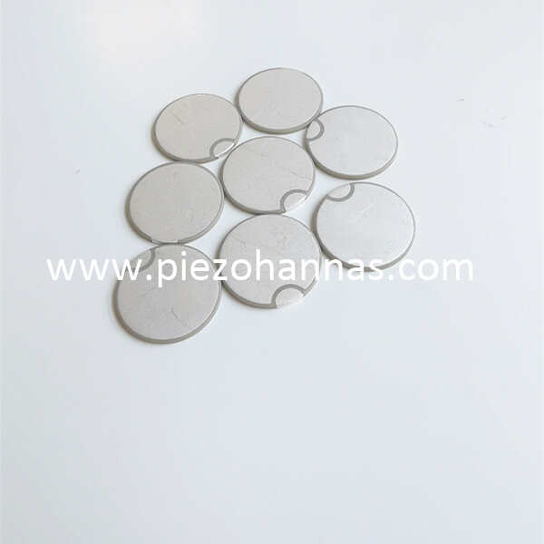
Understanding displacement modes is crucial for mechanical application success. The piezo ceramic polarization direction dictates exactly how the material physically deforms when you apply an electric field. We classify these critical deformations into three primary effects, each suited to different engineering challenges.
First, the longitudinal effect proves best for high-stiffness, high-force applications. You see this mode heavily utilized in heavy-duty ultrasonic welding transducers and high-precision nano-positioning stages. Because the physical expansion aligns perfectly with the poling axis, it transfers immense acoustic or mechanical energy efficiently. The robust nature of this mode allows it to push against heavy loads without failing.
Second, the transverse effect serves as the optimal choice for bending actuators. In these applications, achieving a lower force but a significantly larger deflection represents the primary success criteria. When you apply a voltage, the active material contracts laterally. If bonded to an inactive substrate, this lateral contraction forces the entire assembly to bend dramatically. It is perfect for pneumatic valves and optical deflectors.
Third, the shear effect caters to very specific high-frequency fluid dispensing mechanisms or advanced acoustic scanning arrays. It relies on applying a voltage perpendicular to the poling axis. However, shear designs demand highly controlled bonding techniques and exceptionally precise electrode routing. Any misalignment here introduces parasitic vibrations.
Always use a strict evaluation lens during your design phase. Match the required mechanical outcome directly to the specific displacement mode before finalizing the ceramic formulation. Doing so prevents costly late-stage redesigns.
Component geometry fundamentally influences how we apply polarization and how the finished part behaves in the field. The manufacturing processes, handling procedures, and operational behaviors change drastically based on the chosen shape.
When specifying Piezo Plates and Blocks, you typically deal with standard linear polarization across the thickness. This straightforward, flat geometry makes them much easier to stack. Stacking discrete layers allows you to amplify the longitudinal stroke significantly without increasing the driving voltage to dangerous levels. However, this form factor carries a distinct implementation risk. The outer edges are highly susceptible to stress concentrations. If the electrode margin is not accurately accounted for in the CAD model, these edges act as pivot points and can easily crack under dynamic cyclic loading.
Conversely, Piezo Tubes introduce a completely different set of geometric challenges. They require careful decisions between radial versus axial polarization geometries. Many advanced positioning systems utilize segmented outer electrodes on these tubes to enable precise multi-axis scanning. You will frequently find this specialized setup in atomic force microscopes and precision microfluidic pumps. The primary implementation risk here involves the physical manufacturing constraints. The production process strictly limits the wall thickness-to-diameter ratio for reliable radial poling. If the tube wall is too thick relative to its inner diameter, the internal electric field weakens, making uniform radial poling effectively impossible.
The physical relationship between the electrode plane and the piezo ceramic polarization direction completely determines your required driving voltage. If you increase the distance between the electrodes along the polarization direction, you must simultaneously increase the voltage to maintain the same internal electric field strength. Careful electrode routing and multi-layer structural designs help minimize this voltage demand, keeping the control electronics manageable.
Assembly practices also heavily impact the survival rates of your components. Mounting constraints remain a frequent source of field failure. Applying tight mechanical clamping forces against the non-poling axis can easily induce unwanted cross-talk between displacement modes. In severe cases, off-axis clamping forces will fracture the brittle ceramic material. You must design housing fixtures that support the active axis smoothly without restricting its intended microscopic motion.
Furthermore, soldering and wiring pose significant thermal threats during the assembly phase. High heat applied during soldering to the delicate electrodes can locally exceed the material's Curie temperature. When this threshold is breached, the thermal energy effectively erases the polarization in that specific zone, creating a dead spot. We strongly recommend using low-temperature solders or conductive epoxies. Keep any required soldering heat exposure brief to preserve the delicate internal domain alignment.
Even perfectly poled and perfectly assembled ceramics will fail if pushed beyond their strict operational limits. Understanding these functional thresholds is the best way to prevent unexpected downtime and expensive field replacements.
Thermal limits closely dictate the safe operating temperature range of your device. Operating continuously too close to the Curie temperature agitates the internal crystal lattice. This thermal energy actively degrades the domain alignment, gradually reducing mechanical output until the part becomes inert. Ensure adequate heat sinking if your component operates at high frequencies.
Electrical limits primarily involve the coercive field of the specific ceramic formulation. Exposing the component to a high reversed DC voltage will actively reverse or completely destroy the established polarization direction. Always verify circuit polarity and implement protective diodes before applying power.
Mechanical limits relate directly to applied compressive stress. Applying excessive compressive load parallel to the poling direction can mechanically force the crystal domains to realign to relieve the pressure. This causes a permanent, unrecoverable drop in performance. You must keep dynamic impact forces well below the manufacturer's specified mechanical crushing threshold.
It is important to acknowledge that all PZT ceramics experience a slight, predictable logarithmic aging and decay over time. The stressed crystal domains naturally relax. Proper engineering margins must account for a 2-5% degradation per decade. Factoring this aging process into your software control loops ensures long-term positional reliability.
Moving from a successful benchtop prototype into volume manufacturing requires strict specification guidelines. Ambiguous requests for quotes routinely lead to mismatched components, degraded performance, and expensive project delays. Use a structured approach when ordering your piezo elements.
You must clearly define the following strict requirements for a custom RFQ:
Defined Mechanical Load and Required Stroke: Specify the exact push/pull forces in Newtons and the required travel in micrometers.
Exact Operating Temperature Range: List the continuous ambient temperature and any brief peak thermal exposures the component will endure.
Component Geometry: Provide clear CAD drawings specifying the exact poled and unpoled zones along the ceramic body.
Electrode Configuration: Detail whether you need wrap-around, standard flat, or custom patterned electrodes relative to the poling axis.
Piezo Element Design Parameters Comparison
Design Parameter | Standard Application Profile | High-Performance Profile | Risk of Improper Specification |
|---|---|---|---|
Geometry Aspect Ratio | Length > 3x Thickness | Custom FEA Optimized | Unintended resonance interference |
Electrode Margin Width | 0.2mm to 0.5mm edge | Fully continuous or segmented | High voltage arcing or edge cracking |
Max Operating Temperature | 50% of Curie Temp | Up to 75% of Curie Temp | Permanent thermal depolarization |
We highly recommend engaging application engineers with finite element analysis (FEA) capabilities prior to volume manufacturing. FEA simulations validate the theoretical poling direction against real-world clamping constraints. This software-driven approach highlights dangerous stress concentrations and electrical mismatches long before you pay for the first piece of cut ceramic.
The functional success of a piezoelectric component hinges entirely on marrying the correct geometrical form with the optimal polarization axis. Standardizing external dimensions merely scratches the surface of integration. If the internal crystal domains do not align correctly with your intended electrical and mechanical inputs, the system will inevitably fail.
Treat polarization as a critical structural constraint, not just an electrical one. By evaluating your thermal, electrical, and mechanical boundaries rigorously, you ensure the component survives the assembly process and performs reliably in the field. Careful attention to electrode margins and clamping techniques will save thousands in discarded parts.
Take proactive measures before locking in your final product design. Submit your application parameters or custom blueprints today for a comprehensive engineering review. Our experts will help you determine the most robust and cost-effective polarization and electrode strategy for your specific use case.
A: The driving voltage is proportional to the distance between the electrodes along the polarization axis. Thicker components poled across their length require significantly higher voltage to achieve the same electric field strength compared to thinner, multi-layer designs.
A: While technically possible by heating above the Curie temperature and re-applying a high DC field, it is rarely commercially viable. Repoling alters the mechanical tolerances and can introduce micro-cracks. It is strictly recommended to finalize radial or axial poling requirements during the prototype phase.
A: Datasheet parameters are measured under ideal, unconstrained conditions (free state). Once bonded or clamped in a housing, mechanical impedance and restrictive mounting geometries will suppress the effective displacement, making the operational d33 lower than the theoretical material constant.
A: Applying a field perpendicular to the poling direction initiates the shear mode (d15). If the component was not designed for this—and lacks the appropriate mounting to handle transverse mechanical shear—it can lead to severe structural stress, overheating, or electrical arcing.