Hubei Hannas Tech Co.,Ltd-Professional Piezoceramic Elements Supplier
Hot Keywords:
- All
- Product Name
- Product Keyword
- Product Model
- Product Summary
- Product Description
- Multi Field Search

Views: 2 Author: Site Editor Publish Time: 2021-08-06 Origin: Site


In order to receive low frequency sound waves with high sensitivity, a double sided three-lamination flexural hydrophone was studied, applying the finite element software COMSOL to the simulation and optimization design of the curved hydrophone. The influence of every part on the receiving sensitivity grade of the hydrophone was analyzed to provide the optimal scheme. Finally, we produced a hydrophone prototype and tested it in the water. The maximum size of the hydrophone prototype was 45 mm. The experiment results show that in the receiving frequency range 500 Hz−2.5 kHz, the maximum receiving pressure sensitivity grade was −178 dB, undulating less than 4 dB. The experiment result is the same as that of simulation.
As an underwater acoustic transducer signal receiving device, a sound pressure hydrophone can be used to capture subtle changes in the underwater sound pressure signals, generating a voltage output proportional to the sound pressure, and convert sound energy into electrical signals that are easy to observe, The key equipment for the normal operation of the sonar system is an indispensable and necessary equipment in the underwater acoustic research. However, the existing low-frequency, high-sensitivity hydrophones often have a relatively large size. The three-stacked disc structure of the transducer, the bending vibration mode dominates the vibration, has the characteristics of low resonant frequency, small size, simple structure and so on. However, in the application of the three-stack disc, it is more used on the transmitting transducer or vector hydrophone, and less on the acoustic pressure hydrophone. The disadvantage of low-frequency bending hydrophones is that the working frequency band is very narrow, but like commercially available hydrophones, the bandwidth is very wide, but the sensitivity level is not high. If there is a need to receive sound waves only in a specific low frequency band, the laminations are bent The hydrophone with the structured structure has the advantage of high sensitivity level and has its use value. This paper intends to design a three-lamination curved hydrophone, which takes advantage of the small size and low resonance point of the three-lamination disc, and adopts the design form of connecting two upper and lower three-lamination discs in parallel, and adjusts the fundamental frequency through size optimization. The position of the resonance point is used to realize a small-sized hydrophone with high sensitivity response in low frequency band.
1 The design of the three-lamination curved hydrophone
Three-lamination bending hydrophone, the middle part is a metal ring, the metal ring symmetrically bonds two three-lamination discs up and down, the piezoelectric ceramics of the three-lamination discs are connected in series, and the upper and lower two three-lamination discs are connected in series. Through parallel connection, this structure can make the hydrophone vibrate symmetrically, and is easy to assemble and manufacture.
2 Finite element simulation of hydrophone
COMSOL multiphysics simulation finite element software, with acoustic-piezoelectric interaction module, can be used to analyze multi-physics problems such as fluid-structure coupling in plane wave or spherical wave sound field, and can directly simulate the working scene of hydrophone transducer receiving sound waves in water. And can extract the corresponding voltage of the piezoelectric ceramic surface of the hydrophone to calculate the receiving sensitivity. This article uses COMSOL software to analyze and design the curved hydrophone.
2.1 Finite element simulation model of hydrophone
Use COMSOL multiphysics simulation software to perform finite element analysis on the designed hydrophone. First, establish the finite element model of the hydrophone, and ignore the bonding layer between the piezoelectric ceramic and the metal, the bonding layer between the metals, and the polyurethane rubber potted in the outermost layer in the modeling.Establishing a three-dimensional model of the hydrophone with glue and welded electrode wires, choosing PZT-5 as the piezoelectric ceramic material, choose duralumin, copper or steel as the material for the middle metal disc, and choose copper as the material for the middle metal ring.
2.2 Research on the vibration mode of hydrophone
Using COMSOL software to analyze the characteristic frequency of the hydrophone, you can intuitively obtain the characteristic frequency and vibration displacement of the different vibration modes of the hydrophone. The schematic diagram includes the relative position of each part of the hydrophone in each vibration mode. These analysis results help to better understand the working principle of the hydrophone. The vibration of the first-order vibration mode of a hydrophone of a certain size. This vibration mode is the mode when the hydrophone receives sound waves.
2.3 Structural optimization design of hydrophone
Using COMSOL software to simulate and analyze the working performance of the hydrophone in the water. You can directly establish a water area with a radius of 0.05 m around the hydrophone, and then set a plane sound wave background field with a sound pressure of 1 Pa in the water area to simulate The actual working scenario of the hydrophone in water, the established underwater model of the hydrophone is shown in Figure 4. In the COMSOL analysis setting, the research step selects the frequency domain, so that the response of the entire linear system when subjected to simple harmonic excitation can be analyzed, and the voltage excited by the hydrophone under the action of sound waves of different frequencies can be calculated. Then extract the voltage on the piezoelectric ceramic surface of the hydrophone, and calculate the corresponding receiving sensitivity level of the hydrophone through a formula. Since the hydrophone works in an open-circuit state, the peak of the hydrophone's receiving sensitivity is at its anti-resonance frequency, and the receiving sensitivity level of a underwater hydrophone of a certain size is simulated.
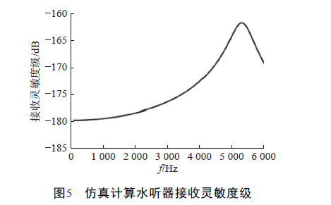
It can be seen from the simulation results that the receiving sensitivity level curve of the hydrophone with this structure is relatively flat in the low frequency band. Next, we will study the dimensional changes of each part of the hydrophone, and the effect of the anti-resonance frequency and the low frequency receiving sensitivity level of the hydrophone Influence. Taking the geometric parameters of the PZT and the metal discs in the tri-stack, and the type of metal materials as variables , the size and fluctuation degree of the designed hydrophone's sound pressure receiving sensitivity level in the low frequency band are taken as the goal, and the hydrophone is carried out. The optimized design of the hydrophone strives to make the sound pressure receiving sensitivity level of the hydrophone in the low frequency band as high as possible and the fluctuations as small as possible. The variables used in the simulation analysis of the controlled variable method are: 1) the material properties of the three laminated metal discs; 2) the ratio of the PZT radius to the metal sheet radius; 3) the ratio of the PZT thickness to the thickness of the metal sheet; 4) the thickness of the three laminated sheets of equal thickness compared with the radius.
2.3.1 Types of PZT and types of metal sheets
Change the type of metal disc in the middle of the three laminations, and obtain the anti-resonance frequency and receiving sensitivity level curve of the hydrophone in water by simulation calculation. The results are shown in Table 1 and Figure 6.
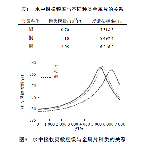
It can be seen from Table 1 that as the Young's modulus of the selected metal gradually increases, the anti-resonant frequency of the hydrophone gradually increases. It can be seen from Fig. 6 that as the Young's modulus of the metal sheet gradually increases, the receiving sensitivity level of the low frequency band of the hydrophone gradually decreases.
2.3.2 Ratio of PZT radius to metal sheet radius
Keep the thickness of the PZT and the intermediate metal sheet unchanged, and take the radius of the intermediate metal sheet as 20 mm. When only the PZT radius is changed, the hydrophone anti-resonance frequency and receiving sensitivity level curves in the water are shown in Figures 7 and 8.
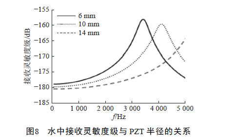
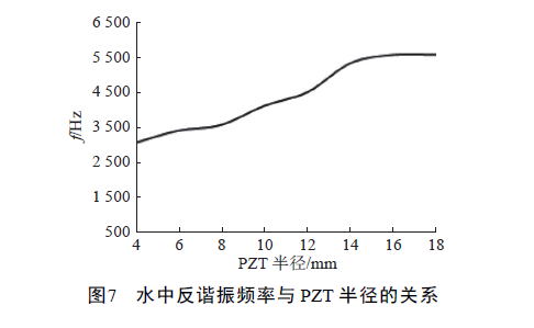
It can be seen from Fig. 7 that as the radius of the PZT increases, the anti-resonant frequency of the hydrophone in the water gradually increases, and when it approaches 20 mm, the anti-resonant frequency hardly increases. Figure 8 shows that as the PZT radius becomes larger, the receiving sensitivity level of the hydrophone in the low frequency band gradually decreases, but the degree of decrease is not large, and the fluctuations are more flat. 2.3.3 The ratio of PZT thickness to metal thickness keeps PZT and the radius of the middle metal sheet unchanged. The thickness of the middle metal sheet is 1 mm, and only the PZT thickness is changed. The anti-resonance frequency and receiving sensitivity level curve of the hydrophone in water are shown in Figure 9 and 10.
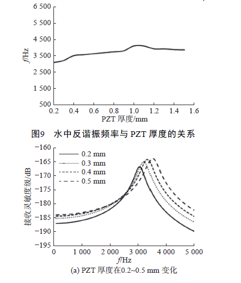
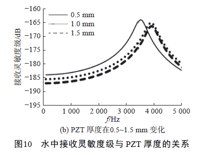
It can be seen from Figure 9 that as the thickness of the PZT increases, the anti-resonant frequency of the hydrophone in water gradually increases. When it reaches the same thickness as the metal sheet of 1 mm, the anti-resonant frequency reaches the maximum, and the PZT thickness continues to increase. The anti-resonant frequency of the hydrophone decreases instead. It can be seen from Figure 10(a) that as the thickness of the PZT increases from 0.2 mm to 0.5 mm, the receiving sensitivity level of the hydrophone in the low frequency band gradually increases, and the fluctuations become more flat. However, when the thickness of PZT is 0.4 mm, the situation is special, and the receiving sensitivity level of the low frequency band suddenly decreases; from Figure 10(b), it can be seen that when the thickness of PZT increases from 0.5 mm to 1.5 mm, the low frequency receiving sensitivity of the hydrophone The level gradually decreases, and the fluctuation is almost unchanged.
2.3.4 Ratio of thickness to radius of three laminated sheets of equal thickness
When the thickness of the metal sheet in the middle layer is the same as the thickness of the PZT, the equivalent electromechanical coupling coefficient of the three-ply sheet is the largest. Next, the influence of the thickness to radius ratio of the three-ply sheet of equal thickness on the underwater operation of the hydrophone is analyzed. Keep the thickness and radius of the three laminated metal sheets of equal thickness unchanged, the PZT radius unchanged, keep the PZT and the metal thickness the same, and only change the thickness of the PZT (metal sheet). As shown in Figures 11 and 12.
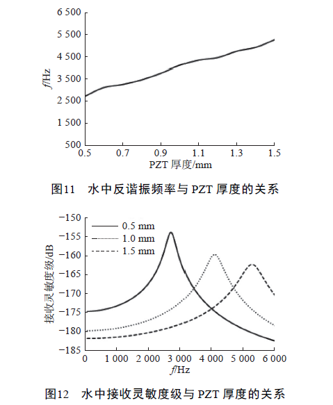
It can be seen from Figure 11 that as the thickness of the PZT (metal sheet) increases, the anti-resonant frequency in the water of the hydrophone gradually increases. In Figure 12, as the thickness of the PZT (metal sheet) gradually increases, the receiving sensitivity level of the hydrophone in the low frequency band gradually decreases, and the fluctuations gradually become smaller.
2.3.5 Regularity analysis
The response change law obtained in the above optimization process can be summarized as follows: 1) As the Young's modulus of the middle metal disc gradually increases, the anti-resonant frequency of underwater communications hydrophone gradually becomes larger, and the receiving sensitivity level of the low frequency band becomes smaller and fluctuates. 2) As the ratio of the PZT to the metal sheet radius becomes larger, the anti-resonant frequency of the hydrophone in water becomes larger, the receiving sensitivity level of the low frequency band decreases, and the fluctuation becomes smaller; 3) As the ratio of the PZT thickness to the metal sheet thickness becomes larger , The anti-resonant frequency of the hydrophone in the water first increases and then decreases, reaching the peak value at a ratio of 1, and the low-frequency receiving sensitivity level first increases and then decreases, reaching the peak at a ratio of about 0.5, and the low-frequency fluctuations gradually decrease; 4) etc. In the thick triple laminate, as the ratio of the thickness to the radius of the PZT (metal sheet) becomes larger, the anti-resonant frequency of the hydrophone in water becomes larger, the receiving sensitivity level in the low frequency band becomes smaller, and the fluctuation becomes smaller. In general, the larger the transducer size, the smaller its resonance frequency, and the fundamental resonance frequency of the hydrophone increases with the increase of the PZT radius or thickness. This is because the hydrophone uses three The flexural vibration mode of the laminated sheet. The main influencing factor of this vibration mode is the stiffness of the triplex. When the PZT radius or thickness increases, the stiffness of the entire triplex becomes greater, so the resonance of the triplex flexural vibration mode The frequency will become larger, making the resonance frequency of the hydrophone larger. The height of the metal ring clamped in the middle of the hydrophone is much smaller than the diameter of the three-layered sheet, and it does not participate in the bending vibration of the three-layered sheet, so the impact on the hydrophone is small.
2.4 Final result
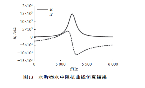
According to the above-mentioned influence law through structural optimization, and taking into account the difficulty of the actual production process of the various parts of the hydrophone, the size parameters of the various parts of the hydrophone are finally determined as shown in Table 2. Use COMSOL software to simulate and calculate the impedance curve of the hydrophone in water. The anti-resonant frequency is 5.2 kHz, as shown in Figure 13.
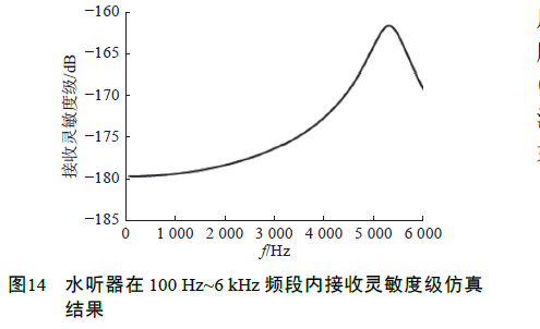
Use COMSOL software to simulate and calculate the receiving sensitivity level of the hydrophone in the frequency range of 100 Hz to 6 kHz, as shown in Figure 14.
Using COMSOL software to simulate and calculate the receiving sensitivity level of the hydrophone in the frequency range of 100 Hz to 6 kHz, as shown in Figure 14.
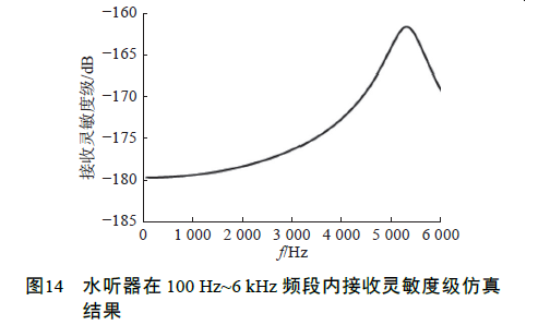
In the low frequency band 100 Hz~2.5 kHz, the receiving sensitivity level of the hydrophone is about −178 dB, and the fluctuation is less than 3 dB, as shown in Figure 15. When the wavelength of the sound wave is much larger than the maximum linear scale of the transducer, the transducer has no directivity. In the working frequency band of the hydrophone, the minimum wavelength when the sound wave frequency is 2.5 kHz is 0.6 m, which is larger than the maximum size of the hydrophone by 0.045 m, it can be considered that the hydrophone has no directivity when receiving sound waves.
3 Production and testing of hydrophone
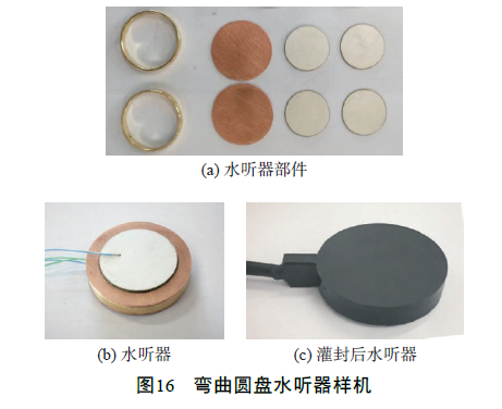
According to the final structural parameters of the hydrophone optimized by COMSOL, the structural components were processed and the hydrophone prototype was made, as shown in Figure 16. After potting, the diameter of the hydrophone is 45 mm and the thickness is 12 mm.
The performance test of hydrophone was carried out in an anechoic pool, the size of the pool was 25 m × 16 m × 10 m, and the comparison method was used for measurement, and a standard hydrophone (B&K 8105) was used for comparison measurement. Pulse signal transmission is adopted, and the distance between the transmitting transducer and the standard hydrophone is 1.5 m (satisfying the far-field condition), and it is placed along the length of the pool with a hanging depth of 4 m. The admittance curve in the water of the prototype hydrophone is finally measured as shown in Figure 17.
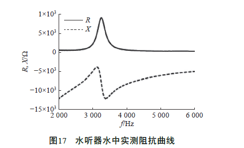
It can be seen from Figure 17 that the anti-resonant frequency of the hydrophone prototype is 3.3 kHz. Due to the limitation of the lower limit of the sound wave frequency that the transmitting transducer used can only transmit 500 Hz sound wave, the lowest frequency of the measuring water receiving sensitivity level curve is 500 Hz, as shown in Figure 18.
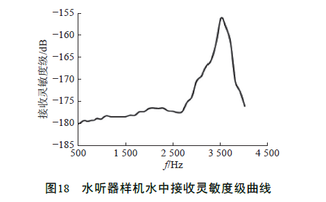
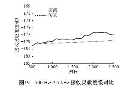
It can be seen from Figure 18 that in the 500 Hz ~ 2.5 kHz frequency band, the receiver sensitivity level of hydrophone is at most −178 dB, and the fluctuation is less than 4 dB. The difference between the measuring and simulated results of the anti-resonant frequency of the hydrophone is mainly due to the fact that the surface of the hydrophone prototype is potted with a layer of watertight polyurethane rubber with a thickness of 2 mm, which will increase the equivalent vibration quality of the hydrophone. It is difficult to simulate this viscoelastic material on the COMSOL simulation software. The assembly accuracy of the structural parts and the bonding process will also have a certain impact on the performance of the hydrophone. The above two factors cause the difference between the measured data and the finite element simulation value. . Compare the measured data of the receiving sensitivity level in the 500 Hz~2.5 kHz frequency band with the simulation results, as shown in Figure 19. In this frequency band, the measured maximum receiving sensitivity level is −178 dB, and the fluctuation is less than 4 dB. The measured data and the simulated value The trend is the same, and the measured data fluctuates slightly larger than the simulated value.
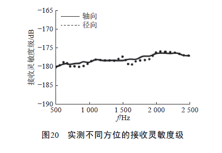
Regarding the receiving sensitivity test of the hydrophone in different azimuths, the axial and radial receiving sensitivity levels of the hydrophone were tested respectively. The test results are shown in Figure 20. The receiving sensitivity level is roughly the same, and it can be considered that the hydrophone has no directivity in the working frequency band of 500 Hz ~ 2.5 kHz.
4 Conclusion
1) Designing and producing a low-frequency bending hydrophone. The measuring hydrophone has a receiving sensitivity level of −178 dB in the frequency band 500Hz−2.5 kHz, and the fluctuation is less than 4 dB. 2.The small-size low-frequency bending hydrophone has realized the characteristics of receiving sound waves with higher sensitivity, which has guiding significance for the application of the bending disc structure in the hydrophone.


 Tech Co,.Ltd")


